INTERNATIONAL ENGINEERING PLANT
ISO 9001:2015 Certified

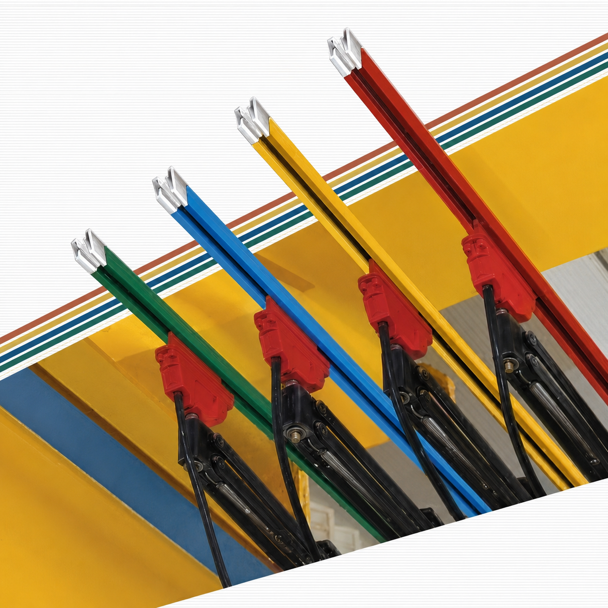
DSL Shrouded Bus Bar System

Insulated, touch‑proof conductor bars for safe power transmission

Down Shop Lead System (DSL) Conductor bar – tracks are super finished and cross section is maintained to achieve required ampere. The material for track is Copper, Aluminum & Galvanize. Conductors shall be accurately aligned to ensure positive electrical contact between the collector and the conductor. Separate conductors shall be provided for each phase. Insulation cover shall be rigid PVC, self extinguishing, with a heat distortion point of 70°C at 260 psi. These conductors are compact, insulated & touch proof. Do not expose live parts. Standard length 4.5 meters.

Bolt Jointed Type Busbar

Bolt Jointed Busbar

ACCESSORIES

Hanger Clamp
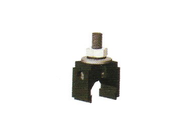
Hanger Clamp

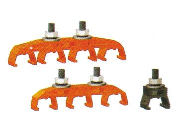
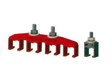
Snap fit type hanger clamp with hardware, required per meter. The conductor bars are clipped in to the hanger clamp. We offer Single Pole, 3 Pole and 4 Pole hanger clamps.

Conductor Joint
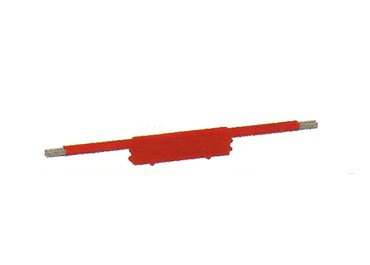
Conductor Joint

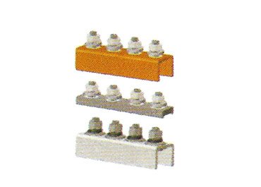
Bolted type jointer provided at each conductor joint. We offer four bolted type jointer with 80mm length to perfect joint of conductors.

Center Power Feed
Center Power Feed

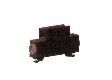
Used for incoming power, easily installed anywhere in the system. One or more power feed points are possible to reduce voltage drop.

Conductor Joint Cover

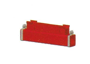
Conductor joints are covered with joint cover, snap fitting with locking arrangement. Required on each conductor joint.

End Cap
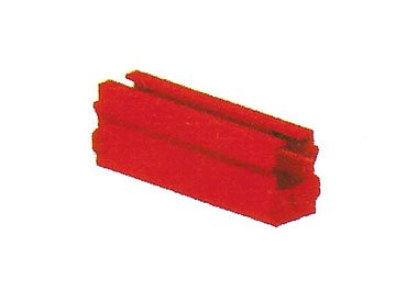
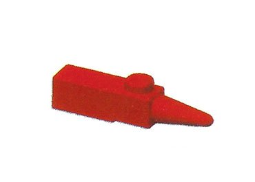
End Cap

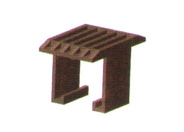
Used to close the end of the conductors, to cover exposed conductor and avoid live contact.

Anchor Clamp
Anchor Clamp

Fall proof protection to the busbar. Required at each 50 meters.

End Power Feed
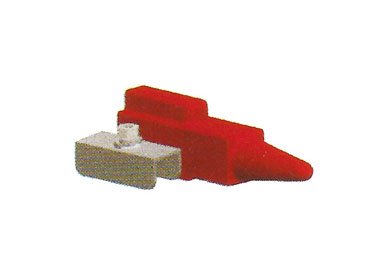
End Power Feed

This accessory is used for incoming power and is fully insulated. Simple clamp type is easily installed at the end of the busbar.

Expansion Joint
Expansion Joint

To accommodate temperature change effects. Required in a single bay length where area is more than 150 meters. Maximum gap 50mm.

DSL System Diagram

Pin Jointed Type Busbar

Pin Jointed Busbar

ACCESSORIES

Hanger Clamp
Hanger Clamp

Snap fit type hanger clamp with hardware, required per meter. We offer Single Pole & 4 Pole hanger clamps.

End Cap / End Power Feed

Used for incoming power and to close the end of conductors. Fully insulated, simple bolted type.

Anchor Clamp
Anchor Clamp

Fall proof protection to the busbar. Required at each 50 meters.

Center Power Feed
Center Power Feed

Easily installed anywhere for incoming power to the conductor rails joint. Multiple feed points possible to reduce voltage drop.

Conductor Joint Cover

Conductor joints are covered with joint cover. Required on each conductor joint.


Current Collector for DSL

Collectors – Current collector assembly consists of a spring loaded sliding contact type shoe of sintered copper graphite. Heavy duty double arm current provides multi axis degree of flexible movement. Exposed part of the current collectors shall be grounded and of corrosion-resistant material. Current collector assembly shall be designed to operate through gaps, splices, switches and shall be self-centering.

IEP CCV-20

IEP CCV-20 (20 AMP)

IEP CCV-125

IEP CCV-125 (125 AMP)

IEP CCW-125

IEP CCW-125 (125 AMP)

IEP CCV-250

IEP CCV-250 (250 AMP)

IEP CCW-250

IEP CCW-250 (250 AMP)

Gravity Type Current Collector for Angle Type DSL

IEP CCAT 125AMP

IEP CCAT 125 AMP

IEP CCAT 250AMP

IEP CCAT 250 AMP


Towing Arm & Busbar Mounting Brackets

MS Angle with slotted hole for mounting of hanger clamp. The towing arm can carry maximum 4 double current collectors. For higher loads please contact us.

IEP TA

IEP TA-40, IEP TA-25 & IEP TA-12

IEP brackets

IEP-500, IEP-400 & IEP-300


C-Rail [Festoon] System

C-Rail Festoon System

Festoon systems are used to electrify various types of mobile equipment. They can be designed not only to support and protect flat and round electrical cables, but air and water hoses as well. Systems can be pre-assembled at the factory to ease installation and reduce time. Festoon systems are typically used on overhead cranes, port cranes and other material handling applications. We also have a solution for extremely corrosive environments. Our product range includes accessories for the various cable management systems. Standard length 4.5 meters.

Hanger Clamp

Hanger Clamp

Jointer

Jointer

Cable Trolley Type S

Cable Trolley Type: S

Starting Trolley

Starting Trolley

End Cap

End Cap

Bracket Set

Bracket Set


Trolley

IEP offers superior quality overhead C-Rail & I-beam trolleys that are expandable to various I-beam sizes, in various load capacity. It consists of a carriage with four wheels containing anti-friction bearings, which are rigidly connected to I-Beam and T-Channel.

CT Type M

CT - Type: M

CT Type H

CT - Type: H

CT Type H1

CT - Type: H

CT Type H2

CT - Type: H

Conductor Bar Table

Voltage Drop

The voltage drop on our conductor system should be restricted to 2.5 to 5% of the nominal supply voltage.

Three Phase Alternating Current (3ph AC): ΔU = √3 × FL × I_total × Z (Volts)
Single Phase Alternating Current (AC): ΔU = 2 × FL × I_total × Z (Volts)
Direct Current (DC): ΔU = 2 × FL × I_total × R (Volts)

Where:
ΔU = Voltage Drop
I_total = Total Currents [Amps]
R = Resistance of conductor [ohms/meter]
Z = Impedance of conductor [ohms/meter]
FL = Feeder Length [Meters]
L = System Length [Meters]
Un = Operating Voltage

If the voltage drop is too high, then either the number of feed points or the cross section of the conductor rail should be increased to reduce the voltage drop along the system.

Multiple feed-in points

  • FL = L     feed from one end
  • FL = L/2   feed from the center
  • FL = L/4   feed from both ends
  • FL = L/6   two feed-in positions, L/6 from each end
  • FL = L/10   feed-in points in the center and at L/10 from both ends
Feed positions diagram

Other possibilities to arrange the feed positions can be selected. For very high current, cables can be connected in parallel (booster cables).

Note: When considering ΔU calculations any effects of additional temperature caused by either heating of the conductor due to duty cycle, or a rise in ambient temperature above 35°C must be considered.